 Most viewed Most viewed |

350 views
|
|

348 views
|
|

347 views
|
|

346 views
|
|
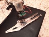
Step 11: solder points of resistor R2 (15k Ohm)345 viewsdesolder resistor R2, locking pliers are one way to pull the resistor leg loose once the solder point is softened
|
|

343 views
|
|
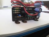
Step 10: resistor R2 (15k Ohm)342 viewsthis is the resistor R2 (15k Ohm) that needs to be replaced with a 10.2k Ohm unit
|
|

341 views
|
|
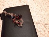
Step 12: resistor R2 (15k Ohm) partialy desoldered341 viewsresistor R2 (15k Ohm) partialy desoldered
|
|
ost_working_chamber340 views
|
|
337 views
|
|
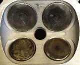
chamber 2 progression336 views
|
|
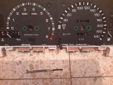
Step 04: fascia screws (4)336 viewsremove the 4 screws holding the two fascia panels in place
|
|

Conversion test successful335 views10.44kOhm instead of 15kOhm
|
|
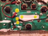
Step 08: screws (5) holding the circuit and motor in place334 viewsunscrew these 5 screws to remove the circuit and motor (the two items are fixed together and come off as one)
|
|
| 3639 files on 243 page(s) |
 |
 |
4 |  |
 |
 |
 |
 |
 |
 |
 |
 |
 |
|