Most viewed Most viewed |
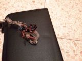
Step 12: resistor R2 (15k Ohm) partialy desoldered704 viewsresistor R2 (15k Ohm) partialy desoldered
|
|
703 views
|
|
702 views
|
|
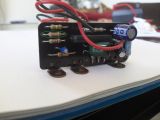
Step 10: resistor R2 (15k Ohm)701 viewsthis is the resistor R2 (15k Ohm) that needs to be replaced with a 10.2k Ohm unit
|
|
699 views
|
|
698 views
|
|
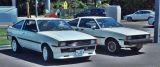
found her twin...???693 views
|
|
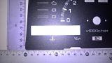
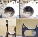
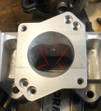
Water/Oil cutout dimensions693 viewsWidth 79.7mm; Height 15.7mm
|
|
693 views
|
|
691 views
|
|
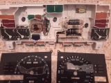
Step 07: circuit and motor revealed690 viewsonce you removed the two fascia panels and light distribution thinggies, the circuit board and motor are revealed - this is what we have to remove in the next step.
|
|

Conversion test successful688 views10.44kOhm instead of 15kOhm
|
|

688 views
|
|

688 views
|
|
687 views
|
|
| 4222 files on 282 page(s) |
 |
|
|
5 | |
|
|
|
|
|
|
|
|
|